الوصف
The output (Y) logic level of an AND gate for all possible inputs A and B is given in the truth table below.
| A |
B |
Y |
| 0 |
0 |
0 |
| 0 |
1 |
0 |
| 1 |
0 |
0 |
| 1 |
1 |
1 |
According to this table, the output is 1 only when both A and B are 1. In other cases the output is 0.
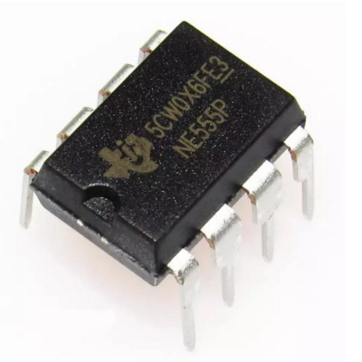
74HC08 Legs

| Leg |
Name |
Explanation |
| 1 |
1A |
1. VE Gate Entry |
| 2 |
1B |
1. VE Gate Entry |
| 3 |
1Y |
1. VE Gate Output |
| 4 |
2a |
2. VE Gate Entry |
| 5 |
2b |
2. VE Gate Entry |
| 6 |
2y |
2. VE Gate Output |
| 7 |
GND |
Soil |
| 8 |
3Y |
3. VE Gate Output |
| 9 |
3A |
3. VE Gate Entry |
| 10 |
3B |
3. VE Gate Entry |
| 11 |
4Y |
4. VE Gate Output |
| 12 |
4A |
4. VE Gate Entry |
| 13 |
4B |
4. VE Gate Entry |
| 14 |
VCC |
Power/Supply Input |
datasheet : 74HC08


المراجعات
لا توجد مراجعات بعد.