


الوصف
cd4001be dip 14 cmos nor gates
The CD4001 is a CMOS chip with four NOR gates. Because each gate has two inputs and it has four gates inside, it’s usually called a Quad 2-Input NOR Gate.
A NOR gate combines the functionality of OR and NOT gates. It gives a HIGH output only when both inputs are LOW; otherwise, the output is LOW.
Pin Overview
| Pin Name | Pin # | Type | Description |
|---|---|---|---|
| VDD | 14 | Power | Supply Voltage (+3 to +15V) |
| GND | 7 | Power | Ground (0V) |
| A1 to A4 | 1, 5, 8, 12 | Input | Inputs A of the four NOR gates |
| B1 to B4 | 2, 6, 9, 13 | Input | Inputs B of the four NOR gates |
| Q1 to Q4 | 3, 4, 10, 11 | Output | Outputs from the four NOR gates |
What is a NOR gate?
A NOR gate is a logic gate that combines the functionality of both an OR and a NOT gate. It’s often called NOT-OR because it’s the same as an OR gate with a NOT gate on the output.
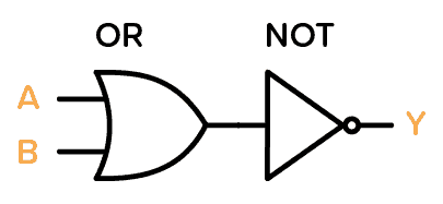
Simply put, a NOR gate gives a HIGH output only when all the inputs are LOW as shown in the truth table below. Therefore, if you input a HIGH in any of the inputs, the result will automatically become LOW since the results of the OR gate are inverted by the NOT gate.
| Input A | Input B | Output Q |
|---|---|---|
| 0 | 0 | 1 |
| 1 | 0 | 0 |
| 0 | 1 | 0 |
| 1 | 1 | 0 |
How To Use the CD4001
First of all, you need a power supply voltage of 3 to 15V. Some versions of the chip support up to 20V. Check the datasheet of your version of the chip for exact values.
To be able to use any of the NOR gates, you need to first connect the VDD pin to the positive terminal and the GND pin to the negative terminal.
The A and B pins are the inputs to the four NOR gates in the IC.
The Q pins are the outputs from the NOR gates.

CD4001 Example Circuit – SR Latch
Here is a practical example that you can build with the NOR gates.
The circuit uses two NOR gates to create an SR latch that turns on and off an LED with separate ON/OFF buttons:
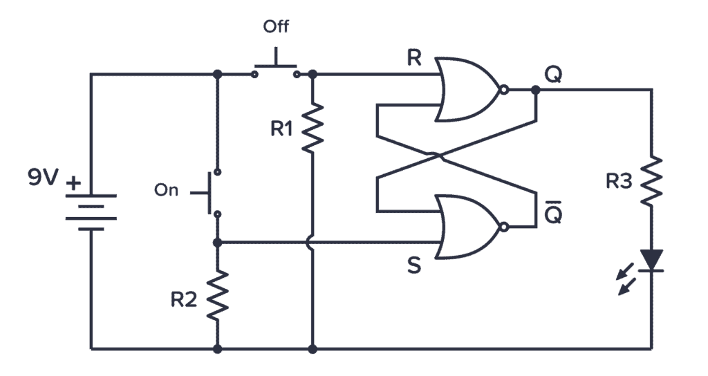
When the On-button is pushed, the LED turns and stays on even after the button is released. The LED stays lit until the Off-button is pushed. To build this you’ll need:
- A Red LED
- Three 10 kΩ resistors
- A chip with NOR gates such as the CD4001BE
Remember that you also need to connect the VDD and GND pins to your power supply in order for the NOR gates to work – even though this is not shown in the circuit diagram.
CD4001 Datasheet
Download the PDF datasheet for the IC 4001 here:

المراجعات
لا توجد مراجعات بعد.